|
NP - Self Clinching Fasteners - Clinch Nuts
|
|
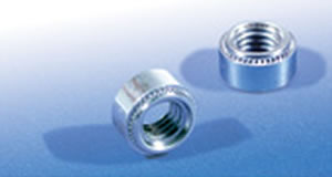 Self Clinching Nuts provide a strong reusable female thread in panels that are too thin to be conventionally tapped.
Utilising a special proven clinch feature, they have excellent torque out and push out characteristics whilst installing flush on the underside of the panel.
Like all self clinching fasteners they are installed using a parallel squeezing action so require access to both sides of the panel.
Available in Steel, Stainless Steel and Aluminium in threads M2 - M10.
|
|
 |
|
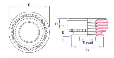
Thread
& Pitch |
Material
Code |
Minimum
Sheet Thickness |
S
Max |
C
Max |
D
± 0.25 |
H
± 0.25 |
Hole Size
in Panel
+ 0.08 - 0.0 |
Min C/L to
edge of panel |
M2 x 0.4* |
0 |
0.8 |
0.77 |
4.22 |
6.30 |
1.5 |
4.25 |
4.8 |
1 |
1.0 |
0.97 |
2 |
1.4 |
1.38 |
M2.5 x 0.45* |
0 |
0.8 |
0.77 |
4.22 |
6.30 |
1.5 |
4.25 |
4.8 |
1 |
1.0 |
0.97 |
2 |
1.4 |
1.38 |
M3 x 0.5 |
0 |
0.8 |
0.77 |
4.22 |
6.3 |
1.5 |
4.25 |
4.8 |
1 |
1.0 |
0.97 |
2 |
1.4 |
1.38 |
Alternative
M3 x 0.5* |
0 |
0.8 |
0.77 |
4.73 |
7.1 |
1.7 |
4.75 |
5.6 |
1 |
1.0 |
0.97 |
2 |
1.4 |
1.37 |
M3.5 x 0.6 |
0 |
0.8 |
0.77 |
4.73 |
7.1 |
1.5 |
4.75 |
5.6 |
1 |
1.0 |
0.97 |
2 |
1.4 |
1.38 |
M4 x 0.7 |
0 |
0.8 |
0.77 |
5.38 |
7.9 |
2.0 |
5.4 |
6.9 |
1 |
1.0 |
0.97 |
2 |
1.4 |
1.38 |
M5 x 0.8 |
0 |
0.8 |
0.77 |
6.38 |
8.7 |
2.0 |
6.4 |
7.1 |
1 |
1.0 |
0.97 |
2 |
1.4 |
1.38 |
M6 x 1.0 |
0 |
1.2 |
1.15 |
8.72 |
11.05 |
4.08 |
8.75 |
8.6 |
1 |
1.4 |
1.38 |
2 |
2.3 |
2.21 |
M8 x 1.25 |
1 |
1.4 |
1.38 |
10.47 |
12.65 |
5.47 |
10.5 |
9.7 |
2 |
2.3 |
2.21 |
M10 x 1.50 |
1 |
2.3 |
2.21 |
13.97 |
17.35 |
7.48 |
14.00 |
13.5 |
2 |
3.2 |
3.05 |
Alternative
M10 x 1.50* |
1 |
2.3 |
2.21 |
12.65 |
14.30 |
6.72 |
12.70 |
11.00 |
2 |
3.1 |
3.05 |
3 |
6.1 |
5.97 |
M12 x 1.75* |
1 |
3.1 |
3.05 |
16.90 |
20.55 |
8.50 |
17.00 |
16.0 |
2 |
6.1 |
5.97 |
*Made to order
|
Materials
|
Finishes
|
|
Carbon Steel
300 Series Stainless Steel (A2)
400 Series Stainless Steel (400) - (Check for availability) Aluminium (AL) (Special Order)
|
Bright Zinc / Trivalent Clear Passivate (ZI)
Other finishes available to order
|
|
The following installation panel material hardness
limitations apply when installing Self Clinching Nuts.
Steel Clinch Nuts: 80HRB Max
Aluminium Clinch Nuts 50HRB Max
300 series Stainless Clinch Nuts: 70HRB max
400 series Stainless Clinch Nuts 90HRB Max
(A special punch/anvil is recommendedfor a proper
installation - call our sales office for further information) |
Part Number Examples |
Type | Thread | Material Code | Finish
i.e. : NS-M3-1-ZI
(Clinch Nut-M3-1mm Min Sheet-Steel-BZP)
i.e. : NS-M4-2-A2
(Clinch Nut-M4-1.4mm Min-Sheet-Stainless Steel) |
|
|
|
Installation Guide for 300 Series
|
|
 |
|
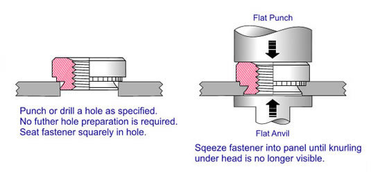
First punch or drill the correct size hole. DO NOT deburr the hole prior to installation as this will remove material required during the clinching process. It is preferable to install the fastener from the side of the panel with the burring or blow through.
Place the fastener in the hole like in the diagram above making sure the part is seated squarely.
Apply a parallel squeezing force until the head is seated against the panel with no serrations visible. Do not over squeeze the fastener into the panel as this will result in the threads being crushed.
When installing Self Clinching fasteners, please pay attention to the minimum hole centerline to edge and parent material hardness limitations.
For special applications or if you are unsure of any aspect about the usage or installation of this fastener, give our sales office a call and we will do our best to offer you a solution or give advice on your application.
|
|
|
Installation Guide for 400 Series
|
|
 |
Thread |
Recommended Anvil Dimensions (mm) |
A ±0.05 |
B Nom |
C +0.03 |
R Max |
M3 |
5.05 |
6.63 |
0.23* |
0.08 |
M3.5 |
5.54 |
7.11 |
0.23* |
0.08 |
M4 |
6.17 |
7.75 |
0.23* |
0.08 |
M5 |
7.34 |
8.89 |
0.23* |
0.08 |
*It is recommended that the anvil is replaced when the C dimension is reduced to 0.13mm due to tooling wear to avoid performance degredation.
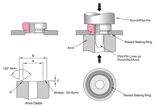
First punch or drill the correct size hole. DO NOT deburr the hole prior to installation as this will remove material required during the clinching process. It is preferable to install the fastener from the side of the panel with the burring or blow through. Minimise local work hardening by punching holes with tooling in good condition.
Place the fastener in the hole like in the diagram above making sure the part is seated squarely.
Apply a parallel squeezing force until the head is seated against the panel with no serrations visible. Do not over squeeze the fastener into the panel as this could result in the threads being crushed.
A special punch/pilot pin combination to align the nut and a special staking ring anvil to aid displacing material into the clinch feature is highly recommended to achieve a proper installation.
A flat punch and anvil can be used but optimum installation/performance may not be achieved.
When installing Self Clinching fasteners, please pay attention to the minimum hole centerline to edge and parent material hardness limitations.
For special applications or if you are unsure of any aspect about the usage or installation of this fastener, give our sales office a call and we will do our best to offer you a solution or give advice on your application.
|
|
|
Performance Data
|
Fastener |
Thread
Size |
Shank
Code |
Test Panel |
Installation
(kN) |
Pushout
(N) |
Torque Out
(Nm) |
Type NS
Steel (ZI)
Stainless (A2)
|
M2
M2.5
M3
|
0 |
Aluminium |
6.70 - 9.0 |
285 |
0.90 |
1 |
402 |
1.15 |
2 |
745 |
1.45 |
0 |
Cold Rolled Steel |
11.0 - 16.0 |
474 |
1.46 |
1 |
555 |
1.68 |
2 |
1014 |
2.10 |
NS 400 Series |
M3 |
0 |
304 Stainless |
13.0 - 23.0 |
590 |
1.60 |
1 |
730 |
1.90 |
2 |
1300 |
2.00 |
Type NS
Steel (ZI)
Stainless (A2)
|
M3.5 |
0 |
Aluminium |
11.0 - 14.0 |
285 |
1.84 |
1 |
410 |
1.90 |
2 |
838 |
2.55 |
0 |
Cold Rolled Steel |
13.0 - 27.0 |
484 |
1.84 |
1 |
574 |
2.29 |
2 |
1213 |
2.31 |
Type NS
Steel (ZI)
Stainless (A2)
|
M4 |
0 |
Aluminium |
11.0 - 14.0 |
301 |
2.31 |
1 |
467 |
2.68 |
2 |
982 |
4.12 |
0 |
Cold Rolled Steel |
17.5 - 28.0 |
495 |
2.90 |
1 |
649 |
4.20 |
2 |
1247 |
5.00 |
NS 400 Series |
M4 |
0 |
304 Stainless |
21.0 - 33.0 |
640 |
3.40 |
1 |
810 |
4.10 |
2 |
1613 |
5.16 |
Type NS
Steel (ZI)
Stainless (A2)
|
M5 |
0 |
Aluminium |
11.0 - 16.0 |
302 |
3.10 |
1 |
475 |
3.55 |
2 |
854 |
5.70 |
0 |
Cold Rolled Steel |
17.5 - 39.5 |
531 |
3.50 |
1 |
798 |
4.56 |
2 |
1120 |
6.91 |
NS 400 Series |
M5 |
0 |
304 Stainless |
26.1 - 42.3 |
812 |
3.90 |
1 |
1031 |
5.10 |
2 |
1779 |
6.82 |
Type NS
Steel (ZI)
Stainless (A2)
|
M6 |
0 |
Aluminium |
17.5 - 33.8 |
981 |
7.95 |
1 |
1579 |
10.31 |
2 |
1612 |
14.02 |
0 |
Cold Rolled Steel |
26.2 - 37.1 |
1377 |
13.24 |
1 |
1771 |
17.49 |
2 |
1774 |
17.62 |
NS 400 Series |
M6 |
1 |
304 Stainless |
39.6 - 49.2 |
2058 |
17.24 |
Type NS
Steel (ZI)
Stainless (A2)
|
M8 |
1 |
Aluminium |
17.8 - 33,9 |
1573 |
13.61 |
2 |
1582 |
18.24 |
1 |
Cold Rolled Steel |
26.3 - 37.3 |
1877 |
18.81 |
2 |
1891 |
20.42 |
Type NS
Steel (ZI)
Stainless (A2)
|
M10 |
1 |
Aluminium |
22.1 - 36.8 |
1758 |
32.58 |
2 |
1763 |
32.76 |
1 |
Cold Rolled Steel |
31.3 - 50.4 |
2017 |
36.53 |
2 |
2023 |
36.76 |
The above data is based on average values obtained in a test environment. Variations in hole size, panel material and installation will effect performance. It is recommended that you carry out your own performance tests in the actual application. Contact our sales department who will be happy to supply samples free of charge.
|
|
|
İndir
Katalog - Broşür
|